Prerequisites
Before beginning the initial rack setup, confirm the following are ready:
Jumpbox or laptop connected to at least one tech port per switch
IPv6 SLAAC enabled on all connected interfaces
SSH connectivity to wicket verified (
ssh wicket@<tech_port_address>)Recovery password chosen and vault ready
TLS certificate PEM file (full chain) and private key PEM file available on jumpbox
rack.tomlvalues prepared (DNS servers, NTP, domain, IP ranges, switch ports, routing)BGP authentication key ready (if applicable)
Network engineer available on standby for connectivity troubleshooting
If any of these items are not ready, return to the Phase 1 Summary Checklist to complete preparation.
Getting started
Since the rack does not have network access at this point, the initial setup is performed by connecting to the technician ports ('techport' in short) on the rack switches via a laptop or jumpbox set up with instructions from Oxide.
The software used for rack component visualization, update, and configuration is known as Wicket. This software runs inside the switch zones on the sleds adjacent to the switches, specifically sleds 14 and 16. Wicket provides a TUI and CLI that allow you to:
Validate component end-to-end connectivity
Update rack software to the latest versions, if necessary
Set up recovery account credentials
Upload a TLS certificate for the
recoverysiloConfigure basic networking such as upstream DNS, NTP, VLAN and routing information
To access a wicket captive shell,
Identify the techport addresses (see Verify IPv6 Connectivity for expected output):
ip neighbor show | grep fdb1
Select any of the techport addresses and ssh in as the wicket user
ssh wicket@${TP_ADDRESS}for example,
ssh wicket@fdb1:a840:2504:195::1
This should give you an Oxide splash screen and land you in wicket showing a graphical display of the rack.
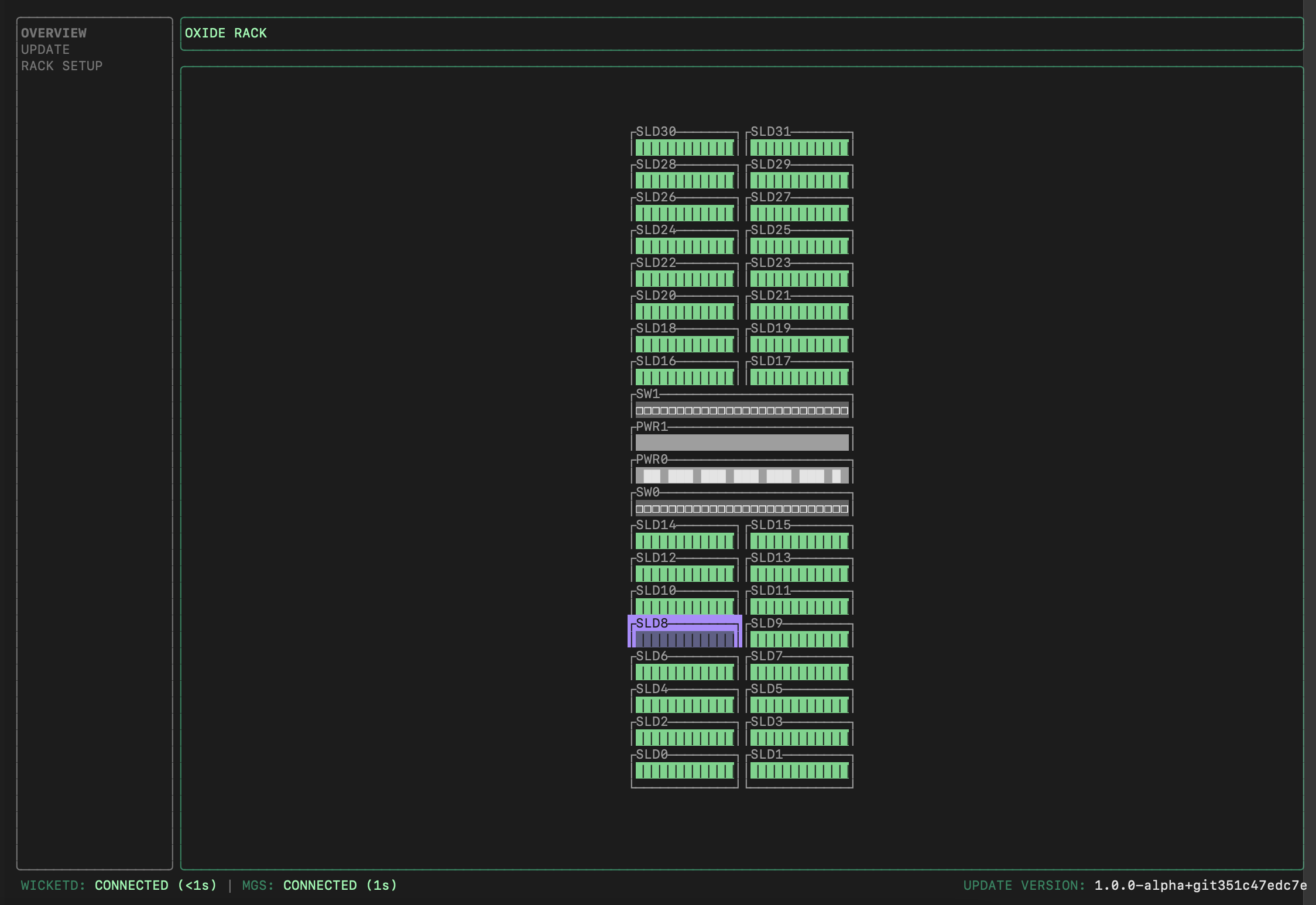
┌─────────────────────────────────────────────────────────────────┐
│ WICKET                                                          │
├──────────────┬──────────────────────────────────────────────────┤
│              │                                                  │
│  OVERVIEW    │  [Main Content Area]                             │
│              │                                                  │
│  > UPDATE    │  Press Tab to focus here →                       │
│              │                                                  │
│  RACK SETUP  │  Component details, status, and configuration    │
│              │  displayed in this area                          │
│              │                                                  │
│              │  Use h/l or ←/→ to navigate within details       │
│              │                                                  │
└──────────────┴──────────────────────────────────────────────────┘

Navigation shortcuts:
  ↑/↓ or j/k    Move between menu items on left
  Tab           Move focus into main content area
  Enter         View details of selected item
  h/l or ←/→    Navigate within detail views
  Ctrl-C        Exit wicket

Key sections:
  OVERVIEW      View rack layout and component status
  UPDATE        Software update management
  RACK SETUP    Initial configuration and setup tasks
Validate component connectivity
Wicket communicates with the Management Gateway Service (MGS) to retrieve information about sled position and identity from the Service Processors (SP) in each Sled, Switch, and Power Shelf Controller (PSC).
To view the sled and switch information:
On the left pane of the Wicket TUI, you can use the up and down arrows (or
j/kfor fans of Vim motions) to select a screen.Select
OVERVIEWand pressTabto move focus into the rack. For every sled displayed, you can pressEnterto see its details.On the sled detail screen, you can use left and right arrows (or
h/l) to move left and right.
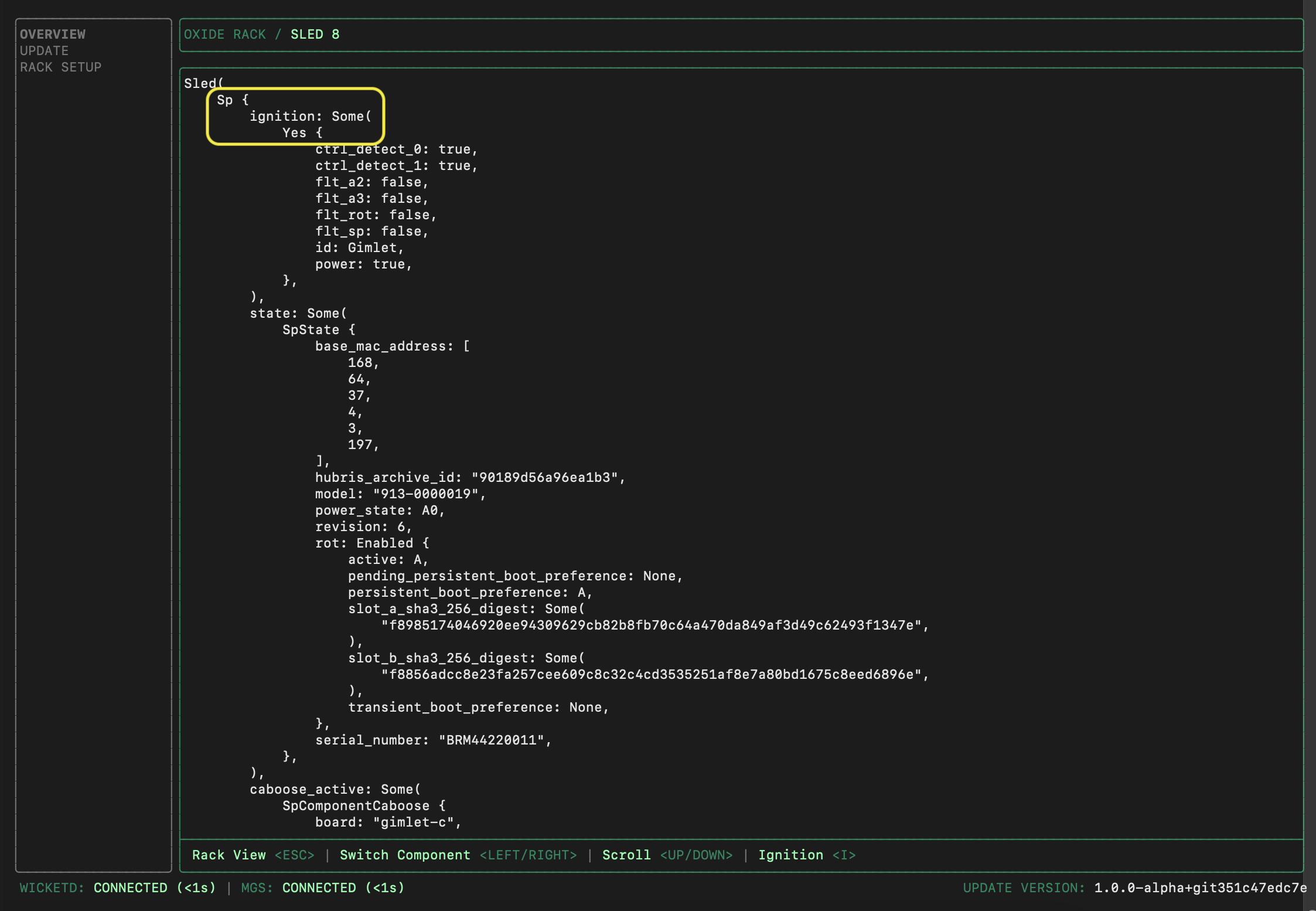
Confirm that the number of sleds with Ignition information matches the expected count (e.g., 16, 24, or 32), and that the two switches and PSC(s) are all powered on.
Verify uplink location and signal quality
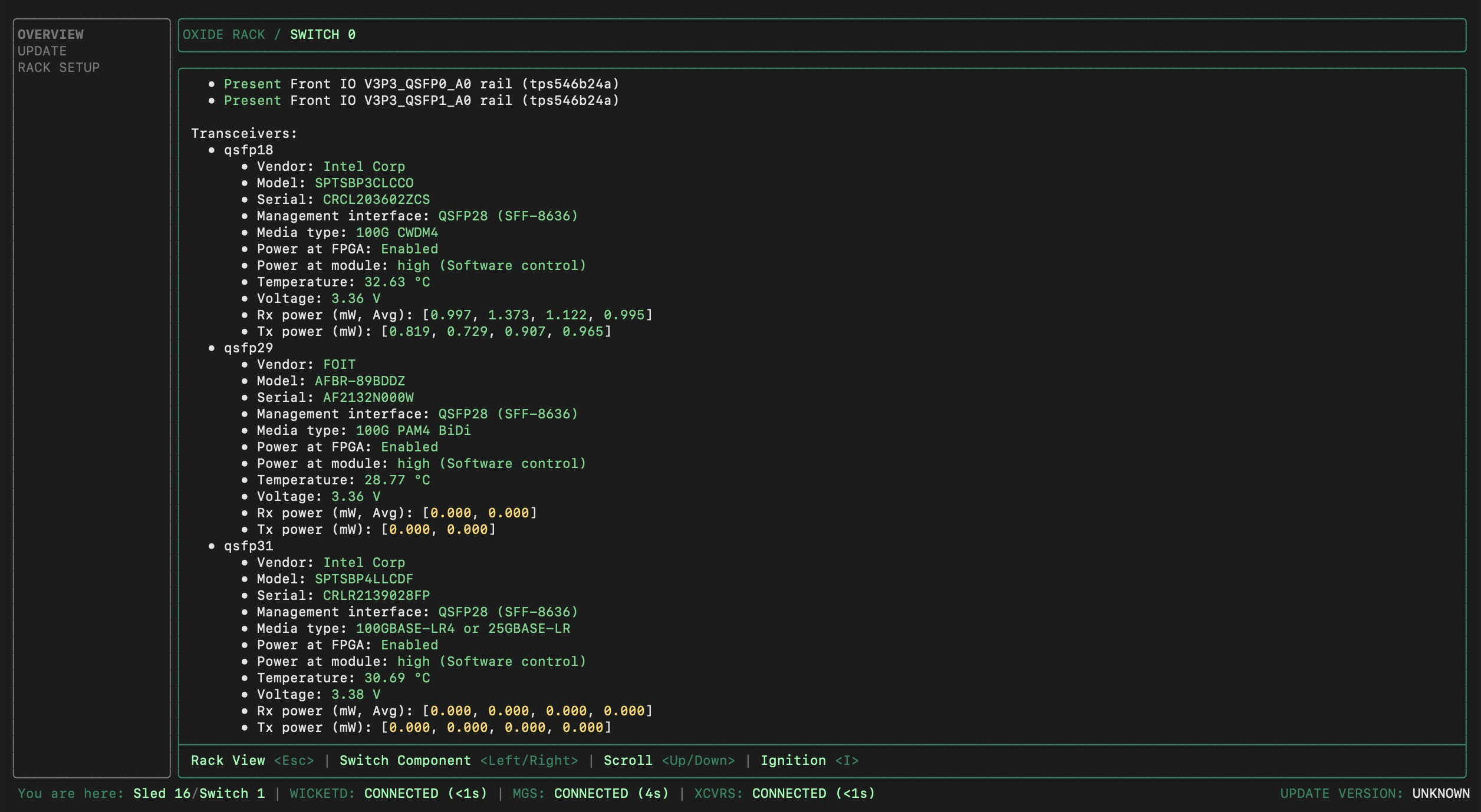
While still in the Wicket OVERVIEW section, review the transceiver status for both Switch 0 and Switch 1 (the information can be found towards the bottom of the switch details page):
Check QSFP port assignments
Verify that the physical fiber connections match the QSFP port numbers you’ll configure in rack.toml.
How to verify:
Note which physical QSFP ports have transceivers installed (wicket displays them as
qsfp0,qsfp1, etc. with power readings).Cross-reference those values with your fiber patch panel documentation or installation notes.
Confirm that the port numbers match what you plan to configure in
rack.tomlunder.
Common issue: The physical port labels on the fiber patch panel may not directly correspond to QSFP numbers. For example, physical "Port 5" on the patch panel might have the identity qsfp5, but some patch panels use different numbering schemes.
rack.toml configuration to match the actual physical ports than to rewire the fibers. Just ensure the correct QSFP port numbers are documented in your rack configuration notes.Check power levels
Verify that detected power levels are within expected ranges:
Rx power values should be between 0.7 - 1.5mW for active channels. (Note: For FR1 or SR1, only channel 1 is applicable; channels 2-4 will show 0.000.)
Tx power values are zero at this point, because the uplinks are not set up yet.
Power at module should be labeled as "high".
Any values highlighted in yellow indicate an abnormal condition, with the exception of the Tx power as noted above. If Rx power values are 0.000 but some Tx power values are non-zero, this may indicate swapped rx/tx cables.
| Reading | Expected Value | Remediation Steps |
|---|---|---|
Rx power | 0.7–1.5 mW per active channel | Clean fiber, reseat transceiver, check for damaged ferrule. |
Tx power | 0.000 (pre-configuration) | Expected to be zero until uplinks are configured — not a fault. |
Rx power = 0, Tx power > 0 | — | Swapped Rx/Tx cables — reverse the fiber pair. |
Power at module | "high" | If not "high", transceiver may not be fully seated. Reseat the transceiver before proceeding. |
Temperature | Green | Do not proceed if values are in yellow, as that indicates overheating. Check airflow and ambient temperature before proceeding. |
Voltage | Yellow | Do not proceed if values are in yellow, as that indicates a power issue. Check power supply status before proceeding. |
For FR1 or SR1 transceivers, only channel 1 is applicable — channels 2–4 will show 0.000 and this is normal.
Check for temperature/voltage anomalies
Wicket provides environmental readings that may indicate potential issues.
If Temperature or Voltage appears in yellow, do not proceed with rack setup, even when the transceivers detect light and power levels appear normal.
After completing the checks, exit wicket by pressing Ctrl-C.
Update rack software
Software updates may be required if newer releases are available post-shipment.
Software updates can be performed by Oxide Support, either onsite or remotely via your secure jumpbox. Self-service updates can also be performed by the operator with coordination from Oxide Support.
The update process is performed in two passes (one per switch and its associated sleds). Each pass takes approximately 30 minutes, with multiple components updating concurrently within each pass. Plan for approximately 1 hour total. During the update, sleds will reboot automatically—this is expected behavior.
Update process overview
The steps below describe how Oxide Support Engineers perform software updates. You do not need to perform these steps, but they are documented here for transparency and to help you understand what the technician will do during your deployment.
The switches and their adjacent sleds are updated one set at a time so that there is always a live wicket to drive the process:
Use the Sled 16 wicket to update Switch 0 and its adjacent Sled 14.
Use the Sled 14 wicket to update Switch 1, PSC(s), and remaining sleds.
Each step takes about 30 minutes in which multiple system components are updated concurrently. For each of the steps:
First, upload the software image zip file to the target wicket with the following command:
ssh wicket@${TP_ADDRESS} upload-repo < tuf-mupdate.zipThen, SSH into Wicket:
ssh wicket@${TP_ADDRESS}Then, initiate the update from the Wicket TUI:
On the left pane of the wicket UI, select
UPDATEand pressTabto move focus into the rack.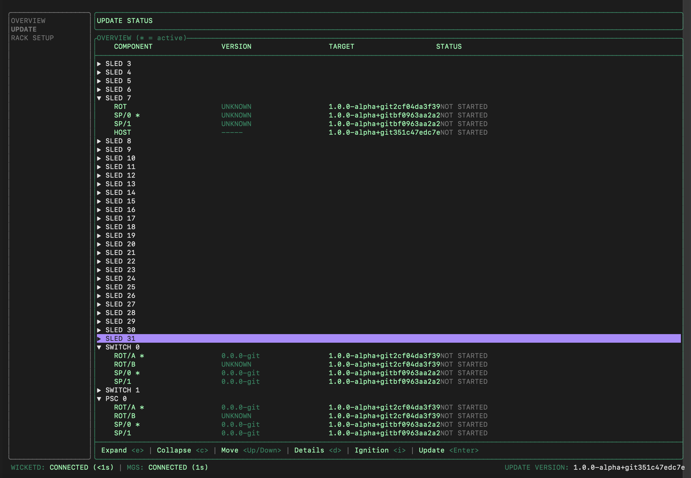
Arrow down to the target sled. You can press the right/left arrows to expand or collapse the short list of versions (there should be only one version available during the first rack install).
Press
Enterand this should take you to another pane with the versions listed at the top, and the bottom should say "Update ready: pressCtrl-Uto start".Press
Ctrl-U, then pressYon the popup to confirm you want to start the update. The bottom pane will be replaced by a list of steps that will be performed.
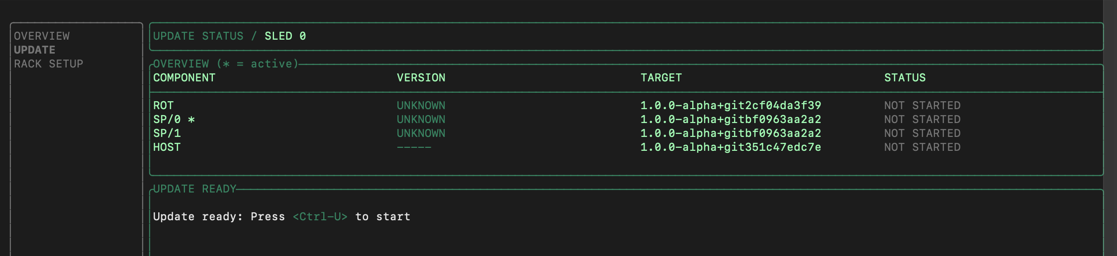
At any time, you can move up and down the list (via up/down/j/k) and press enter to see details about the step. The sleds will be rebooted automatically after update. Here is an example of the update step details:
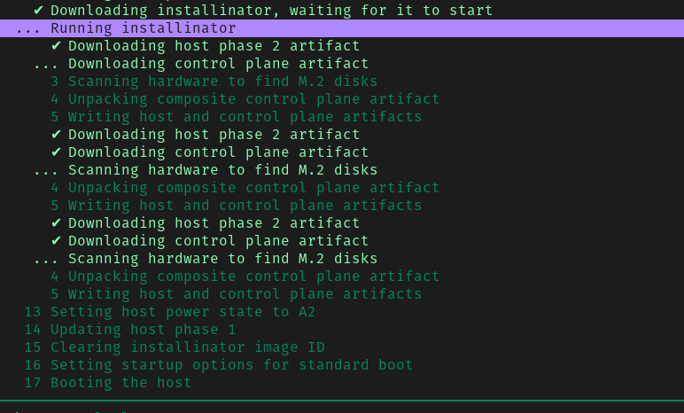
Once all the components have completely booted up, the rack is ready for network configuration.
Configure rack settings
Launch Wicket TUI via any of the available techport interfaces
ssh wicket@${TP_ADDRESS}On the left pane, select RACK SETUP. The current rack status displayed on the right pane will be "Uninitialized" at this point.
While keeping the TUI open, start another terminal session and SSH into the setup CLI:
ssh wicket@${TP_ADDRESS} setupThis should bring up the list of available subcommands:
Usage: wicket setup [OPTIONS] <COMMAND>

Commands:
  get-config        Get the current rack configuration as a TOML template
  set-config        Set the current rack configuration from a filled-in TOML template
  reset-config      Reset the configuration to its original (empty) state
  set-password      Set the password for the recovery user of the recovery silo
  set-bgp-auth-key  Set one or more BGP authentication keys
  upload-cert       Upload a certificate chain
  upload-key        Upload the private key of a certificate chain
  help              Print this message or the help of the given subcommand(s)
In this second terminal window, you will make use of the commands above to enter or upload the necessary rack configurations.
Set recovery user password
A built-in recovery silo (with a system user also named recovery) will
be created by the rack initialization process for setup and recovery purposes.
This is an ordinary silo backed by a local identity provider. The recovery
user has the privileges to create other silos and modify mutable pieces of their
identity provider configuration.
Execute the following subcommand to enter the password for this system user:
ssh -t wicket@${TP_ADDRESS} setup set-passwordUpload TLS certificate
The Oxide Console and API will be hosted under the domain name controlled by your
organization. In this step, you will upload a TLS certificate and private
key that corresponds to the subdomain delegated to the Oxide Rack. This TLS
certificate is used for the recovery silo but generally a TLS certificate
with a wildcard DNS SAN is generated so it can be used for user-created silos
as well.
For example, given a delegated DNS name of cloud.acme.com one can generate
a TLS certificate with a DNS SAN of *.sys.cloud.acme.com to use it for both
the recovery silo (i.e., recovery.sys.cloud.acme.com) and user-created
silos (i.e., silo01.sys.cloud.acme.com). Alternatively, one could generate
a TLS certificate with a DNS SAN specific to each silo but that would have to be
done each time a new silo is created.
With a TLS certificate in hand, execute the upload-cert subcommand to import
the TLS certificate chain file:
ssh wicket@${TP_ADDRESS} setup upload-cert < ${CERT-CHAIN}.pemand then upload-key to import the key file:
ssh wicket@${TP_ADDRESS} setup upload-key < ${CERT-KEY}.pemValidation: The system will validate that:
The certificate chain is complete (leaf + intermediate + root CAs).
The certificate is not expired.
The private key matches the certificate’s public key.
Common errors and solutions:
| Error Message | Solution |
|---|---|
"Certificate chain incomplete" | Ensure your PEM file includes all certificates in the chain. Concatenate them in order: leaf certificate first, followed by intermediate CAs, then root CA. |
"Certificate and private key do not match" | Verify you’re uploading the correct key file that corresponds to this certificate. Use |
"Certificate expired" | Generate a new certificate with a valid expiration date. Check certificate validity with |
"Invalid PEM format" | Ensure files are in PEM format (Base64-encoded with |
Validation: After uploading, the Wicket TUI should show the certificate details under the RACK SETUP section. Verify:
Certificate Subject/CN matches your domain.
Expiration date is in the future.
No error messages appear in the wicket status.
If the certificate fails validation, wicket will display an error message. Common issues and fixes are listed in the table above.
Configure basic networking
In this step, you will configure the endpoints of boundary services that integrate with the Oxide Rack. You will supply the information in the form of a text file in toml format.
To begin the configuration, retrieve the toml template via
ssh wicket@${TP_ADDRESS} setup get-config > rack.tomlPlanning Sheet Value rack.toml Field ───────────────────────────────────────────────────────────────────── Delegated domain: → external_dns_zone_name = cloud.acme.com "cloud.acme.com" External DNS IPs: → external_dns_ips = 203.0.113.10, 203.0.113.11 ["203.0.113.10", "203.0.113.11"] Uplink gateway: → nexthop = 198.51.100.1 "198.51.100.1" Infrastructure IP range: → infra_ip_first = "198.51.100.64" 198.51.100.64/26 (64 IPs) infra_ip_last = "198.51.100.127" Uplink ports: → port = "qsfp5" Switch 0 qsfp5, Switch 1 qsfp5 (in both switch configs) Transceiver type: → uplink_port_speed = "speed100_g" 100GBASE-FR1 uplink_port_fec = "none" Upstream switch ASN: → asn = 65001 65001 (in BGP peer config) ───────────────────────────────────────────────────────────────────── TIP: Use this mapping to translate values from your pre-installation checklist into the correct rack.toml configuration fields. Double-check that port numbers, IP addresses, and ASN values match exactly.
The content of the file should look like this:
# Delegated external DNS zone name
#
# The rack provides separate external API and console endpoints for each Silo.
# These are named `$silo_name.sys.$external_dns_zone_name`.  For a Silo called
# "eng" with delegated domain "oxide.example", the API would be accessible at
# "eng.sys.oxide.example".  The rack runs external DNS servers that serve A/AAAA
# records for these DNS names.
external_dns_zone_name = ""

# IP addresses for authoritative external DNS servers operated by the rack for
# the DNS domain delegated to the rack by the customer. Each of these addresses
# must be contained in one of the "internal services" IP Pool ranges listed
# below.
external_dns_ips = [
]

# External NTP servers; e.g., "ntp.eng.oxide.computer".
ntp_servers = [
]

# External DNS server IP Addresses; e.g., "1.1.1.1", "9.9.9.9".
dns_servers = [
]

# Ranges of the service IP pool which may be used for internal services.
#
# Elements of this list should be of the form:
#
#    { first = "first_ip", last = "last_ip" }
#
# where `last_ip` is equal to or higher than `first_ip`; e.g.,
#
#    { first = "172.20.26.1", last = "172.20.26.10" }
internal_services_ip_pool_ranges = [
]

# List of sleds to initialize.
#
# Confirm this list contains all expected sleds before continuing!
bootstrap_sleds = [
   (list of sleds auto-discovered from the rack will be displayed here)
]

# Allowlist of source IPs that can make requests to user-facing services.
#
# Use the key:
#
# allow = "any"
#
# to indicate any external IPs are allowed to make requests. This is the default.
#
# Use the below two lines to only allow requests from the specified IP subnets.
# Requests from any other source IPs are refused. Note that individual addresses
# must include the netmask, e.g., "1.2.3.4/32".
#
# allow = "list"
# ips = [ "1.2.3.4/5", "5.6.7.8/10" ]
[allowed_source_ips]
allow = "any"

# network config
[rack_network_config]
infra_ip_first = ""
infra_ip_last = ""

# A table of ports to initialize on the rack. The keys are the switch (switch0,
# switch1) and the port name (qsfp0, qsfp1, etc). Copy and paste this section
# for each port.

[rack_network_config.switch0.qsfp0]

    # Routes associated with this port.
    # { nexthop = "1.2.3.4", destination = "0.0.0.0/0" }
    routes = []

    # Addresses associated with this port.
    # "1.2.3.4/24"
    addresses = []

    # `speed40_g`, `speed100_g`, ...
    uplink_port_speed = ""

    # `none`, `firecode`, or `rs`
    uplink_port_fec = ""

    # Whether or not to set autonegotiation: `true` or `false`
    autoneg = false

    # A list of BGP peers for this port. Copy this section, changing the port name
    # as desired. Remove if not needed.
    [[rack_network_config.switch0.qsfp0.bgp_peers]]

        # The autonomous system number (required). This must match one of the `asn`
        # values in the `[[rack_network_config.bgp]]` section.
        asn = 0

        # The switch port the peer is reachable on (required).
        port = ""

        # The IPv4 address of the peer (required): e.g. 1.2.3.4.
        addr = ""

        # How long to keep a session alive without a keepalive, in seconds.
        hold_time = 6

        # How long to keep a peer in idle after a state machine reset, in seconds.
        idle_hold_time = 3

        # How long to delay sending open messages to a peer, in seconds.
        delay_open = 0

        # The interval in seconds between peer connection retry attempts.
        connect_retry = 3

        # The interval to send keepalive messages at, in seconds.
        keepalive = 2

        # Require that a peer has a specified ASN (optional).
        # remote_asn = 0

        # Require messages from a peer have a minimum IP time to live field (optional).
        # min_ttl = 0

        # If BGP authentication is desired, a key identifier. Multiple peers
        # can share the same key ID, if desired.
        #
        # The actual keys are provided via `wicket setup set-bgp-auth-key`.
        # Currently, only TCP-MD5 authentication is supported.
        # auth_key_id = "key1"

        # Apply the provided multi-exit discriminator (MED) for updates sent to the
        # peer (optional).
        # multi_exit_discriminator = 0

        # Include the provided communities in updates sent to the peer (optional).
        # communities = [28, 47]

        # Apply a local preference to routes sent to the peer (optional).
        # local_pref = 0

        # Enforce that the first AS in paths received from the peer is the
        # peer's AS.
        enforce_first_as = false

        # Apply import policy to this peer with an allowlist of prefixes
        # (optional). Defaults to allowing all prefixes. Use an empty list to
        # indicate that no prefixes are allowed.
        # allowed_import = ["224.0.0.0/8"]

        # Apply export policy to this peer with an allowlist of prefixes
        # (optional). Defaults to allowing all prefixes. Use an empty list to
        # indicate that no prefixes are allowed.
        # allowed_export = []

        # Associate a VLAN ID with this BGP session (optional).
        # vlan_id = 0

[rack_network_config.switch1]

# Optional BGP configuration, as a list of entries. Duplicate or remove this
# section as needed.
[[rack_network_config.bgp]]

# The autonomous system number.
asn = 0

# Prefixes to originate e.g., ["10.0.0.0/16"].
originate = []
Annotated Configuration Example
The following is a complete, worked example for a rack with:
Delegated domain:
cloud.acme.com.Two DNS servers at Cloudflare and Quad9.
Corporate NTP server.
20-address services pool (172.20.26.1–20).
Static routing with one uplink per switch.
# ─── Upstream Services ───
# These DNS servers must be recursive resolvers (IP addresses only, no hostnames).
# They are used by rack infrastructure AND provided to guest VMs via DHCP.
dns_servers = [
    "1.1.1.1",
    "9.9.9.9",
]

# NTP servers can be IP addresses or DNS names.
ntp_servers = [
    "ntp.acme.com",
]

# ─── Names and Numbers ───
# The domain delegated to the Oxide rack. Silos will be at $silo.sys.cloud.acme.com
external_dns_zone_name = "cloud.acme.com"

# IPs for the Oxide-hosted DNS servers. These must fall within the services pool below.
# You will configure your upstream DNS to delegate cloud.acme.com to these addresses.
external_dns_ips = [
    "172.20.26.1",
    "172.20.26.2",
]

# Services pool — used by DNS, API, NTP, and other rack services.
# Minimum: 13 addresses. Recommended: 20.
# The external_dns_ips above must be within this range.
internal_services_ip_pool_ranges = [
    { first = "172.20.26.1", last = "172.20.26.20" }
]

# ─── Sled Discovery ───
# Auto-populated list of sleds detected during boot. Verify the count matches
# your expected configuration (16 for half-rack, 32 for full rack).
bootstrap_sleds = [
    # (auto-discovered sled list will appear here)
]

# ─── Source IP Allowlist ───
# "any" allows all external IPs to access the rack API and console.
# Change to "list" with specific subnets to restrict access.
[allowed_source_ips]
allow = "any"

# ─── Switch Uplink Configuration ───
# Infrastructure IPs are assigned to switch uplink ports. You need one IP per uplink.
# These must be on the same subnet as the upstream gateway.
[rack_network_config]
infra_ip_first = "172.20.15.21"
infra_ip_last = "172.20.15.22"

# Switch 0, port qsfp0 — VERIFY this matches the physical port you plugged fiber into!
[rack_network_config.switch0.qsfp0]
    routes = [{ nexthop = "172.20.15.17", destination = "0.0.0.0/0" }]
    addresses = ["172.20.15.21/29"]
    uplink_port_speed = "speed100_g"    # Must match your transceiver (speed40_g, speed100_g, speed200_g)
    uplink_port_fec = "rs"              # "rs" (Reed-Solomon) or "none"
    autoneg = false

# Switch 1, port qsfp0
[rack_network_config.switch1.qsfp0]
    routes = [{ nexthop = "172.20.15.17", destination = "0.0.0.0/0" }]
    addresses = ["172.20.15.22/29"]
    uplink_port_speed = "speed100_g"
    uplink_port_fec = "rs"
    autoneg = false
Key points:
The
qsfp0in[rack_network_config.switch0.qsfp0]must match the physical port number where the transceiver is inserted. If your fiber is in port 31, useqsfp31.uplink_port_speedvalues arespeed40_g,speed100_g, orspeed200_g— note the underscore format.Each
addressesentry must use an IP from theinfra_ip_first/infra_ip_lastrange.An address can only be assigned to one switch port. Using the same address on multiple ports will cause an error.
internal_services_ip_pool_ranges are used for Control Plane DNS and API services. The pool range(s) must cover 16 or more IP addresses.qsfp0 with the actual qsfp port in use for uplink connection.Use a text editor such as vim to edit the toml file. Upon completing the configuration data entry, you can upload the file via
ssh wicket@${TP_ADDRESS} setup set-config < rack.tomlThe configurations should be refreshed automatically in the wicket UI with the uploaded data.
Validation: After uploading, verify in the wicket RACK SETUP screen that:
All DNS servers are displayed correctly
NTP servers are listed
External DNS zone name matches your delegated domain
External DNS IPs are within your services IP pool range
Services IP pool shows the correct ranges
Both switches show uplink port configurations
Uplink port numbers (qsfp__) match physical fiber connections
Uplink speeds match your transceiver type (40G, 100G, or 200G)
BGP configurations appear (if using BGP)
No error messages appear at the bottom of the wicket UI
If you see errors or the configuration looks incorrect, edit with reset-config, get-config, and set-config, then re-upload.
Common configuration mistakes
The following mistakes are frequently encountered during initial rack setup. Check for these before kicking off initialization:
| Issue | Symptom | Solution |
|---|---|---|
QSFP port mismatch — | Rack initialization succeeds but no external connectivity. | Verify that the physical port label matches the config, make corrections in |
Services pool too small — fewer than 13 addresses. | Rack initialization fails or control plane is unstable. | Allocate at least 16 addresses (13 minimum, 20 recommended). |
DNS servers not recursive — authoritative-only DNS IPs provided. | Rack services cannot resolve external names; NTP sync fails. | Use recursive resolvers (e.g., 1.1.1.1, 8.8.8.8, or your corporate recursive DNS). |
Certificate SAN mismatch — cert is for | Browser shows TLS errors when accessing the Oxide Console. | Regenerate cert with SAN |
Certificate missing chain — only leaf cert uploaded, no intermediates. | Some clients cannot validate the TLS cert. | Include the full chain (leaf + intermediates + root) in the PEM file. |
Wrong FEC setting — | The link comes up, but either drops packets or shows errors. | Match the FEC setting with your upstream port config (typically |
Infra IP not on same subnet as gateway — CIDR mismatch. | No connectivity from the rack to routers upstream. | Ensure that the uplink address and gateway are on the same subnet. |
Duplicate infra IPs — same address on multiple switch ports. |
| Each address can only be assigned to one switch port. |
Forgot DNS delegation — no NS records pointing to rack DNS IPs. |
| Configure NS records in your upstream DNS to delegate to the |
Firewall blocking services — rack can’t reach DNS/NTP. | Time sync and/or DNS resolution fail; causing initialization to hang. | Ensure firewall allows UDP 53 (DNS) and UDP 123 (NTP) outbound from the services IP pool. |
What's the symptom?
│
├─→ Rack won't initialize
│   ├─ Check: Services pool size ≥ 13 addresses?
│   │  Fix: Add more IPs to services_ip_pool_ranges
│   ├─ Check: DNS servers are recursive resolvers?
│   │  Fix: Use 8.8.8.8 or your corporate recursive DNS (not authoritative)
│   └─ Check: Firewall allows UDP 53/123 outbound?
│      Fix: Allow services IP pool → DNS/NTP servers
│
├─→ No external connectivity after initialization
│   ├─ Check: QSFP port number matches physical port?
│   │  Fix: Verify qsfp port in rack.toml matches patch panel connection
│   ├─ Check: FEC setting matches upstream switch?
│   │  Fix: Align uplink_port_fec with upstream (none/RS/BASE-R)
│   └─ Check: Infra IP subnet matches gateway subnet?
│      Fix: Ensure infra_ip_first/last are in same subnet as nexthop
│
├─→ Can't reach rack console (https://)
│   ├─ Check: DNS delegation configured?
│   │  Fix: Add NS records pointing to external_dns_ips
│   ├─ Check: Certificate SAN covers *.sys.<domain>?
│   │  Fix: Regenerate cert with correct wildcard SAN
│   └─ Check: Full certificate chain uploaded?
│      Fix: Include leaf + intermediate + root CA in PEM
│
└─→ Time sync or DNS resolution failures
    ├─ Check: DNS servers are recursive (not authoritative)?
    │  Fix: Replace with recursive resolvers like 8.8.8.8
    └─ Check: Firewall allows UDP 53/123 from services pool?
Fix: Add firewall rules for DNS/NTP from services IPsSpecify VLAN tag
If you use VLAN tagging for the control plane or data plane, you will need to configure the VLAN tag in the switch port settings. Here is an example:
[rack_network_config.switch.qsfp31]
uplink_port_speed = "100G"
uplink_port_fec="none"
autoneg = false
# for tagged control plane traffic
addresses = [{address = "198.51.103.10/30", vlan_id = 100}]
# for tagged data plane traffic
bgp_peers = [
    {asn = 47, addr = "198.51.103.9", port = "qsfp31", vlan_id = 100},
]
routes = []
Enter BGP auth key values
If your network configurations do not involve BGP authentication, you can skip to the next step to start rack initialization.
You will reference the auth_key_id entered in the toml file uploaded in
set-config to specify the keys associated with each of the key ids.
For example, for the following BGP peer:
[[rack_network_config.switch0.qsfp31.bgp_peers]]
  asn = 47
  addr = "198.51.103.9"
  port = "qsfp31"
  local_pref = 20
  auth_key_id = "bgpkey"
you can set the password associated with that key as follows:
$ ssh -t wicket@${TP_ADDRESS} setup set-bgp-auth-key 'bgpkey'
current BGP authentication keys (0/1 set):
  • bgpkey: unset
You will then be prompted for a password. Upon filling in the password you’ll see something like this (with a different SHA-256).
setting 1 key to use TCP-MD5 authentication
  • (1/1) add bgpkey:
          ✓ key added: TCP-MD5 (SHA-256: 650e9595236154547665929c8ff6c06a4e1f89bb63797649b3cfc5337d075be8)
✓ 1/1 key set
Connection to fdb1:a840:2504:2d7::1 closed.
The auth key pairs entered will also be reflected in the rack configurations displayed in the wicket UI.
Kick off rack initialization
Review the rack configurations in the wicket UI. If everything looks correct,
you can kick off the rack setup by pressing Ctrl-K. The process takes about
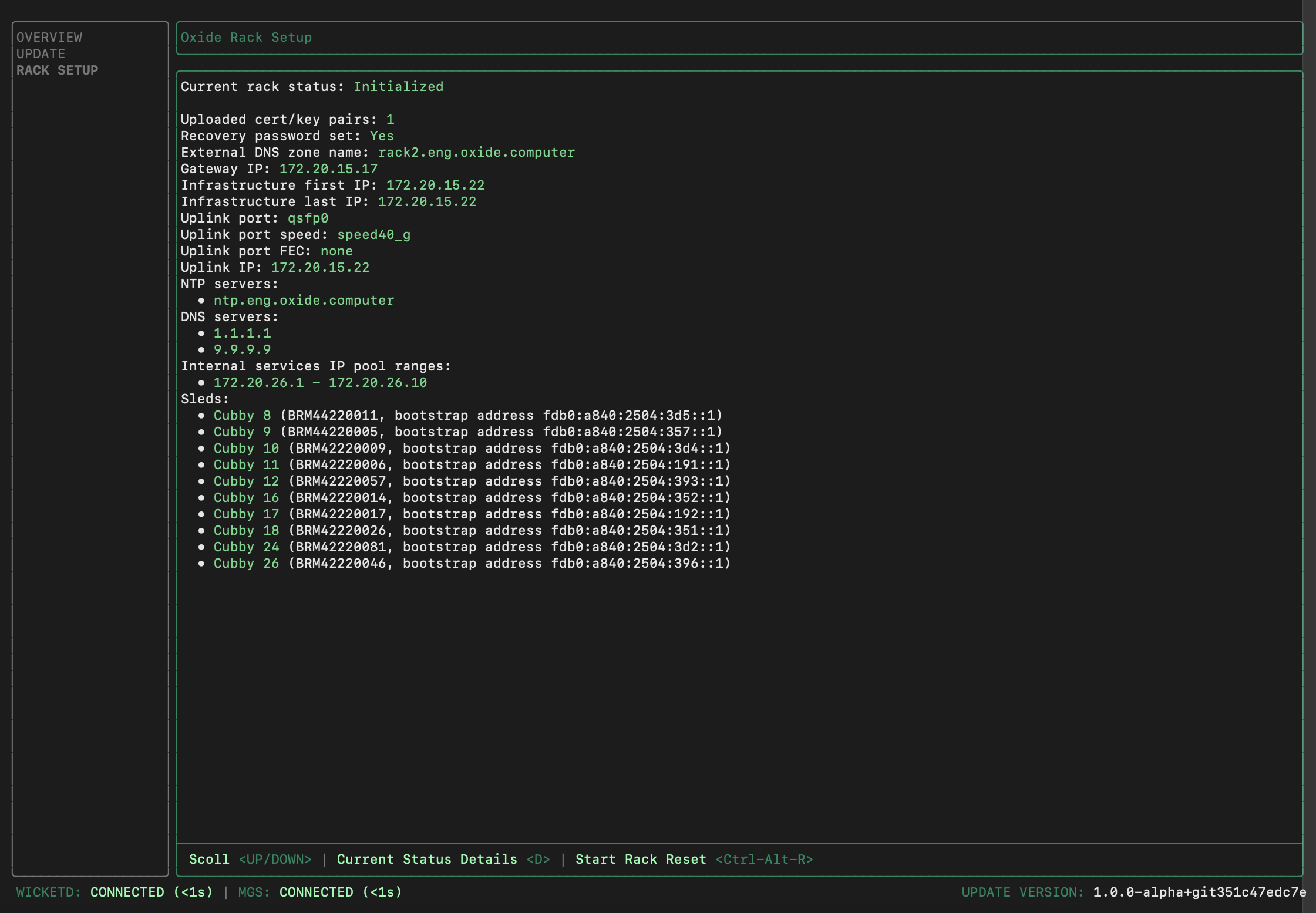
15-20 minutes. Once the initialization has completed, the Current rack status
will become Initialized. Here is an example of the final state:
Success criteria and troubleshooting
How to know initialization succeeded:
The Current rack status changes from "Initializing" to "Initialized"
No error messages appear in the wicket status panel
The progress indicator reaches 100% and stops
All services listed show "Running" status
If initialization stalls or fails:
| Issue | Solution |
|---|---|
Progress stalls at specific percentage for >10 minutes | Check network connectivity to DNS and NTP servers; verify firewall allows UDP 53 and UDP 123 |
Error: "Cannot reach external DNS" | Verify the DNS server IPs in rack.toml are recursive resolvers and reachable from the services IP pool |
Error: "Time synchronization failed" | Verify NTP servers are reachable; check firewall rules for UDP 123 |
Error: "Insufficient IP addresses in services pool" | This operation requires modifying the RSS configuration file and reinitializing the rack. Contact Oxide Support. |
Any other error or timeout after 30 minutes | Contact Oxide Support with the error message and wicket status screenshot |
When to contact Oxide Support:
Initialization fails with an error you cannot resolve from the table above
Initialization completes but DNS resolution for
recovery.sys.<domain>failsAny component shows "Failed" status after initialization
Initialization hangs for more than 30 minutes with no progress
What’s next
The rack control plane is now running. Proceed to the final configuration phase:
Phase 4: Rack Configuration — Create silos, integrate identity providers, configure IP pools, and deploy a test VM (1-2 hours with identity and operations teams)
You’ll access the rack via the web console at https:/ using the recovery password you set during this phase.