This document describes how an Oxide rack is connected to a broader network. The following is a high-level checklist of things to consider when planning for the oxide rack.
Need to connect between 2 and 4 RJ45-based Ethernet cables to the rack for management, with at least one connection for each switch.
The management network requires IPv6.
Decide what type of transceiver to use for the data network from the supported transcievers list.
Set up management and data network firewall rules.
Plan out a set of names and addresses to assign to the rack.
Plan a routing strategy between the rack and the broader network.
Before you begin
Gather the following information before starting network planning. You will need all of these values during rack setup:
Upstream DNS server IP addresses (max 3) — must be recursive resolvers.
NTP server addresses (max 3) — may be DNS names or IP addresses.
A DNS domain to delegate to the rack (e.g.,
cloud.acme.com).IP address ranges for Oxide infrastructure services (min 13, recommended 20 addresses).
IP address ranges for virtual machine instances.
IP addresses for switch uplink ports (one per uplink).
Gateway/next-hop IP for each uplink (static routing) or BGP peer addresses and ASN (BGP routing).
Optical transceiver type from the supported list.
If using BGP, also prepare: your ASN, originate prefixes, hold/keep-alive timers, and MD5 auth key if applicable.
This guide covers the physical network setup, management network configuration, and data network planning required to prepare your environment for the Oxide rack.
Physical setup
The Oxide rack has two middle-of-rack switches.
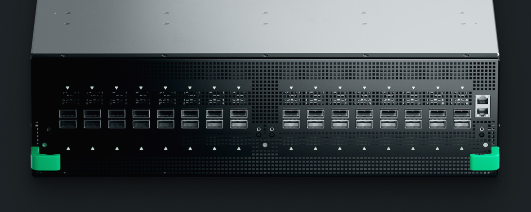
Each switch has 32 QSFP-compatible ports that can operate at either 40 Gbit/s (QSFP), 100 Gbit/s (QSFP28), or 200 Gbit/s (QSFP56). There are also two RJ45 ports that will be referred to as technician ports. The technician ports are 10/100/1000BASE-T capable.
Transceiver selection
When planning your network integration, you must determine:
How many transceivers per switch — Each switch supports up to 32 QSFP ports. Typically, 2-4 transceivers per switch (4-8 total) are sufficient for uplink connectivity, providing redundancy across switches.
What type of transceiver — The transceiver type you select determines the fiber cable specifications required. Choose based on your datacenter’s existing fiber infrastructure and distance requirements.
The following table shows supported QSFP transceiver types.
| Type | Fiber | Strands | Fiber Bundle CPN |
|---|---|---|---|
40GBASE-LR4 | Single-Mode | 2 (LC) | 991-0000208 LC Duplex OS2 |
40GBASE-SR4 | Multi-Mode | 8 (MPO/MTP) | 991-0000211 MTP/MPO-12 OM4 |
100GBASE-CWDM4 | Single-Mode | 2 (LC) | 991-0000208 LC Duplex OS2 |
100GBASE-FR1 | Single-Mode | 2 (LC) | 991-0000208 LC Duplex OS2 |
100GBASE-LR4 | Single-Mode | 2 (LC) | 991-0000208 LC Duplex OS2 |
100GBASE-SR4 | Multi-Mode | 8 (MPO/MTP) | 991-0000211 MTP/MPO-12 OM4 |
100GBASE-SR-BiDi | Multi-Mode | 2 (LC) | 991-0000209 LC Duplex OM4 |
100GBASE-SWDM4 | Multi-Mode | 2 (LC) | 991-0000209 LC Duplex OM4 |
200GBASE-FR4 | Single-Mode | 2 (LC) | 991-0000208 LC Duplex OS2 |
200GBASE-SR4 | Multi-Mode | 8 (MPO/MTP) | 991-0000211 MTP/MPO-12 OM4 |
Uplink port configuration
You must configure upstream switch ports connected to the Oxide rack with a Maximum Transmission Unit (MTU) of 1500 or above. If you plan to enable jumbo frames for instances, the uplink ports need an MTU of at least 9000.
Management network
The management network is how the rack is first set up and is accessible through the technician ports. The management network provides access to:
A terminal UI program called
wicketthat allows administrators to:Provide an initial configuration for the rack and bring the system online.
Perform out-of-band system updates.
A support shell that allows Oxide support engineers to troubleshoot low-level system issues.
The details of using these programs are covered in the Initial Rack Setup guide. This guide will focus on the network aspects of technician ports.
Technician port isolation
Addressing
Technician port addresses are auto-configured via SLAAC or DHCPv6:
SLAAC addressing
To use this address assignment method, interfaces plugged into technician ports must be configured for IPv6 autoconfiguration (SLAAC) so that they can receive the periodic IPv6 advertisements from technician ports every 30 seconds.
When the device plugged into the technician port receives a SLAAC advertisement, it will auto-assign an address on the IPv6 network advertised by the rack’s technician port. For example if the technician port advertises a prefix
fdb1:a840:2504:195::/64
the connected device will assign an address in that space, typically based on
the MAC address of the interface it’s connected on
following EUI-64
conventions. For example, if the connected interface has a MAC address of
2:8:20:36:5c:8d, the resulting self-assigned IPv6 address on the advertised
technician port prefix would be the following.
fdb1:a840:2504:195:8:20ff:fe36:5c8d/64
The technician port assigns the first address in this range to itself. So for the example prefix above, you can reach services provided by the rack over the technician port at the following address.
fdb1:a840:2504:195::1
Each technician port advertises a distinct IPv6 / prefix.
DHCPv6 addressing
Technician port addresses are assigned by the upstream network device they are connecting to.
When technician ports are configured with DHCPv6 addresses, there are limitations in place. In particular:
The rack underlay network
/prefix (auto-generated or explicitly configured during rack setup) is routed internally within the rack.48 The rack bootstrap network
fdb0:a840:25::/is routed internally within the rack.40
These / and / prefixes will not be reachable from rack technician
ports.
Firewall considerations
In order to access the services provided over the management network, SSH port
22 must be accessible. Both the wicket program and the support shell are
accessed through TCP port 22.
Data network

The data network is accessible through the rack switch QSFP ports. The data network provides connectivity between services and instances running inside the rack and the broader network the rack is a part of. Services running inside the rack include:
In order for the rack to function correctly, it needs access to a few services on the broader network, including the following.
NTP servers
Upstream DNS servers
Layer 3 routing architecture
The rack switches operate as Layer 3 routers, not Layer 2 switches. There is no common broadcast domain shared between ports. Key implications for your network design:
Egress traffic: Each active port requires an egress route assigned to forward packets to the broader network.
Ingress traffic: The rack does not respond to ARP or NDP requests for IP pool addresses. Upstream routes for internal-services and instance prefixes must use the corresponding rack-side uplink address as their next hop. The rack responds to ARP or NDP for that uplink address, not for addresses in the routed pools.
Routing integration: Plan for the rack switches to integrate with your existing routing infrastructure using static routes or BGP.
In the examples below, each uplink uses a dedicated / point-to-point subnet
containing one address for the upstream router and one for the rack switch.
The 172.20.15.20/ range is used to pair the upstream router at .20 with the rack at .21, and
the 172.20.15.22/ range pairs the rack at .22 with the upstream router at .23.
Initial configuration overview
Configure initial communication paths between your network and the rack using a configuration file (rack.toml). The wicket setup program handles this configuration during the Initial Rack Setup phase.
The sections below detail the network-specific configuration parameters. A complete configuration example appears at the end of this guide.
Broader network services
The first part of the initial setup config tells the rack how to access the
services it needs on the broader network. Here we are telling the rack that it
can use 1.1.1.1 and 9.9.9.9 as upstream DNS servers and it can use
"ntp.acme.com" as a time source.
In the examples that follow IPv4 is used. However, IPv6 is also supported. The
upstream DNS servers provided to dns_servers must be recursive resolvers
and must be specified as IP addresses. These DNS servers are used for rack
infrastructure and provided to end user instances via DHCP options. The NTP
servers provided to ntp_servers may be DNS names or IP addresses. There is a
limit of 3 DNS servers and NTP servers.
dns_servers = [
    "1.1.1.1",
    "9.9.9.9",
]

ntp_servers = [
    "ntp.acme.com",
]
Assignment of names and numbers to the rack
The DNS names and IP address numbers assigned to the rack from the broader network include.
A DNS domain with a subdomain for each Silo.
A set of IP addresses for routing between rack switches and the broader network.
A set of IP addresses for rack-hosted DNS servers.
A set of IP addresses for the Oxide API server.
A set of IP addresses for end-user instances.
In this example, the DNS name cloud.acme.com is assigned to the rack. The
DNS servers for the broader network infrastructure will need to delegate
cloud.acme.com to the IP addresses described below and use glue records to
forward DNS requests to the rack hosted DNS servers. DNS names for Oxide
silos will be created under the sys.cloud.acme.com DNS name (e.g.,
$siloName.sys.cloud.acme.com).
The IP addresses that will be used by the rack to host DNS servers are set as
172.20.26.1 and 172.20.26.2. These are just example addresses, and we’ll
generally use addresses from this subnet for the rest of this example. The only
limitation on these addresses is that there must be at least two provided. Once
the rack control plane is up, these addresses will respond to DNS queries.
Critically, you will be able to resolve the address for the recovery silo
via recovery.sys.cloud.acme.com.
The internal-services IP pool provides the rack with a set of addresses to assign to rack-hosted services such as the Oxide API, DNS, etc. Generally speaking, IP pools are a resource that the rack control plane uses to dynamically allocate IPs. In this case, we are defining an IP pool for internal services. IP pools are also used for end user instances and can be defined using the Oxide API once the rack is initialized. These are addresses from the broader network that are assigned to the rack. It’s recommended to assign at least 16 addresses to the rack for high-availability (HA) setups. A minimal HA setup uses the following addresses:
5 addresses for DNS.
3 addresses for the Oxide API.
2 addresses for boundary NTP daemons.
DNS addresses are specified explicitly in configuration. Other address types are allocated dynamically from the provided IP pool. Oxide silo API addresses are discoverable via the external DNS servers by querying for records of the form:
$siloName.sys.cloud.acme.comOn initialization the rack automatically sets up the recovery silo which is
accessible using the recovery.sys.cloud.acme.com DNS name.
external_dns_zone_name = "cloud.acme.com"

external_dns_ips = [
  "172.20.26.1",
  "172.20.26.2",
]

internal_services_ip_pool_ranges = [
    { first = "172.20.26.1", last = "172.20.26.16" }
]
IP address planning
The rack uses three categories of IP addresses, each serving a different purpose:

The set of addresses infra_ip_first and infra_ip_last at the beginning of
the configuration define a range of addresses that may be assigned to rack
switches. These addresses may be used exactly once. An attempt to assign the
same address to multiple switches or to multiple ports on the same switch will
result in an error. This constraint may be relaxed in a later release when
anycast addresses become supported. This range is inclusive meaning the first
and last addresses are included in the range.
Next, an uplink port is configured for each rack switch. In this example one uplink is configured per switch. However, there is no limit to the number of uplinks that may be configured here.
Each uplink configuration includes the following.
gateway_ip: the address of the upstream router that will provide off-subnet communications for the rack on this uplink.port: specifies which switch port this configuration applies to. The ports on the switch are physically labeled with a number. In this configuration that number is prefixed with"qsfp".uplink_port_speed: the speed of the transceiver module plugged into the QSFP port.uplink_port_fec: the forward error correction mode to be used for the port. This can currently bersfor Reed-Solomon ornone.uplink_cidr: the IP and subnet mask in CIDR format to assign to this port. This address must be pulled from theinfra_ipaddress range.switch: which rack switch this configuration applies to, may be eitherswitch0orswitch1.
[rack_network_config]
infra_ip_first = "172.20.15.21"
infra_ip_last = "172.20.15.22"

[[rack_network_config.ports]]
routes = [{nexthop = "172.20.15.20", destination = "0.0.0.0/0"}]
addresses = ["172.20.15.21/31"]
port = "qsfp0"
uplink_port_speed = "100G"
uplink_port_fec = "rs"
bgp_peers = []
switch = "switch0"

[[rack_network_config.ports]]
routes = [{nexthop = "172.20.15.23", destination = "0.0.0.0/0"}]
addresses = ["172.20.15.22/31"]
port = "qsfp0"
uplink_port_speed = "100G"
uplink_port_fec = "none"
bgp_peers = []
switch = "switch1"
Complete configuration
The following is all of the above configuration in one place.
#
# Broader network services
#

dns_servers = [
    "1.1.1.1",
    "9.9.9.9",
]

ntp_servers = [
    "ntp.acme.com",
]

#
# Assign names and numbers to the rack
#

external_dns_zone_name = "cloud.acme.com"

external_dns_ips = [
  "172.20.26.1",
  "172.20.26.2",
]

internal_services_ip_pool_ranges = [
    { first = "172.20.26.1", last = "172.20.26.16" }
]

#
# Configure rack switches
#

[rack_network_config]
infra_ip_first = "172.20.15.21"
infra_ip_last = "172.20.15.22"
bgp = []

[[rack_network_config.ports]]
routes = [{nexthop = "172.20.15.20", destination = "0.0.0.0/0"}]
addresses = ["172.20.15.21/31"]
port = "qsfp0"
uplink_port_speed = "100G"
uplink_port_fec = "rs"
bgp_peers = []
switch = "switch0"

[[rack_network_config.ports]]
routes = [{nexthop = "172.20.15.23", destination = "0.0.0.0/0"}]
addresses = ["172.20.15.22/31"]
port = "qsfp0"
uplink_port_speed = "100G"
uplink_port_fec = "none"
bgp_peers = []
switch = "switch1"
Rack switch configuration with BGP
Setting up BGP as a part of rack setup requires supplying two types of information.
A set of BGP router configurations must be specified as a part of the
rack_network_config.Each port that peering will take place over must have a BGP peer config for each neighbor.
The BGP router config below configures a router with an autonomous system number
of 47. This router will announce the prefix 172.20.26.0/ to any peers it
establishes BGP sessions with.
[[rack_network_config.bgp]]
asn = 47
originate = [ "172.20.26.0/24" ]
The port configurations that follow are a direct translation from the previous
static routing configurations to BGP. Here the routes field is empty and the
bgp_peers field filled in. Because each rack switch can have multiple BGP
routers running on different ASNs, peers must specify which ASN they are in.
Each peer configuration also specifies the address of the neighbor it is
expecting to peer with.
port field of BGP peers is redundant with the port field of the
rack_network_config.ports port field and will be removed in a future
release.[[rack_network_config.ports]]
routes = []
addresses = ["172.20.15.21/31"]
port = "qsfp0"
uplink_port_speed = "100G"
uplink_port_fec = "rs"
bgp_peers = [{asn = 47, addr = "172.20.15.20", port = "qsfp0"}]
switch = "switch0"
[[rack_network_config.ports]]
routes = []
addresses = ["172.20.15.22/31"]
port = "qsfp0"
uplink_port_speed = "100G"
uplink_port_fec = "none"
bgp_peers = [{asn = 47, addr = "172.20.15.23", port = "qsfp0"}]
switch = "switch1"Additional configurations such as timeout, filters, and MD5 authentication key can be included in the initial setup or added at a later time. A complete list of the supported configurations can be found in the Configuring BGP guide.
BGP configuration planning
If you plan to use BGP, prepare the following values. Sharing a sanitized copy of your upstream switch configuration with Oxide ahead of installation is the most effective way to ensure all settings are covered.
| Parameter | Value | Notes |
|---|---|---|
Oxide rack ASN | The AS number for the Oxide switches | |
Originate prefixes | Prefixes the rack will announce to BGP peers | |
TCP-MD5 authentication | Yes / No | Auth key will be entered interactively during setup |
Hold time | Seconds (default: 6) | |
Keep-alive time | Seconds (default: 2) | |
Connect retry interval | Seconds (default: 3) | |
Remote/customer ASN | Per-peer; may differ per uplink | |
Import filters | Allowed prefixes to import (default: all) | |
Export filters | Allowed prefixes to export (default: all) |
Beyond initial setup
This guide has primarily focused on network considerations for getting the rack up and running. Once the rack is set up, there are additional considerations for transiting traffic to and from VM instances. The Oxide API provides a set of endpoints for managing IP pools. These IP pools are the same basic abstraction as the internal services IP pool covered above. The only difference is the IP pools that are managed through the Oxide API are used to hand out IP addresses to VM instances. The addresses in these pools need to be routed to the rack, and the rack needs to have egress routes set up pointing at appropriate gateways for the address space covered by the IP pool.
The configuration provided during initial rack setup may be changed later through the Oxide API once the rack is up and running. You may also make other network topology changes, such as:
Expanding connectivity to additional upstream physical networks for higher availability, or
Connecting the rack to other cloud providers through private transit networks.
Firewall considerations
The following ports are used by the rack and should be made available on the
broader network segment the rack is a part of. The direction in identifies
traffic to the rack from the broader network, out identifies traffic from
the rack to the broader network, and both indicates bidirectional traffic.
| Port | Protocol | Direction | Usage |
|---|---|---|---|
443 | TCP / HTTPS | in | Oxide rack API |
53 | UDP / DNS | both | Name resolution for rack services (out). Rack provided name resolution (in). |
123 | UDP / NTP | both | Network time protocol (NTP) message exchange. |
179 | TCP / BGP | both | Border gateway protocol (BGP) peering and prefix exchange between the rack and broader network routers. |
4784 | UDP / BFD | both | Bidirectional forwarding detection (BFD) messaging. The Oxide platform uses BFD for Multihop Paths as described in RFC5883. |
22 | TCP / SSH | in | SSH access to instances. Not strictly required for rack functionality but likely needed by end users. |
Upstream router considerations
Summary: If the Oxide rack and its upstream gateway share a common L3 interface, cross-VPC traffic may trigger ICMP Redirect exception processing on the upstream router, degrading performance. Disable ICMP Redirects on upstream routers connected to the Oxide rack to avoid this issue.
ICMP Redirect messages are a mechanism for an IP router to inform a sender of a better path to their destination which doesn’t require the use of that router. Because of the security implications of allowing a network path to be influenced by an unauthenticated third party device, ICMP Redirect messages are typically ignored when received. However, some network vendors enable the generation of ICMP Redirect messages on their platforms by default.
On most modern router or switch platforms, packets are handled by specialized silicon called Network Processors, which are designed to provide high throughput and consistent low latency. However, there are some packets which require more specific handling than the Network Processor is capable of; these packets are called "exceptions" and are sent to the platform’s CPU for the Operating System to perform the required handling. Exception handling imparts negative performance characteristics on affected packets, since the bandwidth of the link connecting the Network Processor to the platform’s CPU is limited (and often exacerbated by traffic policers intended to protect the platform’s control plane) and latency may be non-deterministic as a result of the OS' process scheduling. One exception condition that is commonly present in Network Processors enables the platform to generate ICMP Redirect messages. A packet satisfies this condition when the Network Processor determines that the route lookup for the packet’s Destination IP is resolved via the same Layer 3 interface that the packet was received on.
The processing sequence for packets matching the ICMP Redirect exception generally looks like this:
Parse the Source IP and Destination IP of the exception packet
Perform a route lookup against the Destination IP of the exception packet and identify the next-hop
Generate an ICMP Redirect message, indicating the sender can route to the Destination IP via the next-hop from our routing table, rather than via this router
Send the ICMP Redirect towards the Source IP of the exception packet
Send the exception packet via the next-hop from our routing table

In a network where ICMP Redirects are both generated and trusted, the sender can update its forwarding path to avoid the hairpinning router, and packets should only traverse the exception path temporarily. However, in the majority of cases, ICMP Redirects are not trusted by hosts and packets would continue to traverse the exception path indefinitely. In this scenario, all such packets would be negatively impacted by the CPU-based exception handling.
The network isolation that Oxide provides for VPCs does not allow traffic to directly flow from one VPC to another without first exiting the rack. This allows for an intermediate device to apply its own security policies on cross-VPC traffic. For example, some operators may want to ensure traffic inspection is conducted for all network traffic that flows between two different tenants. Because of this strict network isolation and the need to traverse an intermediate device, normal cross-VPC packets may be considered exceptions by an upstream router. To avoid performance issues with cross-VPC traffic due to exception processing, ICMP Redirects may need to be disabled on the upstream routers connecting to an Oxide system.