This guide covers connecting an Oxide rack to your network after physical installation and power connection are complete. For physical installation procedures (uncrating, positioning, power connection), see the Facilities Guide.
Prerequisites
Confirm that the following facilities work is complete before proceeding:
Rack uncrated and positioned (see Facilities: Physical Installation).
Power connected and validated (see Facilities: Power Connection).
And that all rack LEDs are solid:
All power shelf LEDs are solid (no blinking or red/amber indicators).
All sled power LEDs are solid.
Both switches power LEDs are solid.
Additionally, confirm that the following are on-site and ready:
Requested compatible (transceivers) are present and plugged into the rack.
Network uplink fiber and RJ45 cables for technician port(s).
Jumpbox or technician laptop with IPv6 SLAAC enabled.
Connect uplink fiber
If not already present, insert the optical transceivers into the planned QSFP ports on each switch and connect the fiber patch cables from your upstream network equipment to the patch panel on the top of the rack.
Depending on your rack version, the patch panel layout may differ. Refer to the appropriate diagram for your rack:
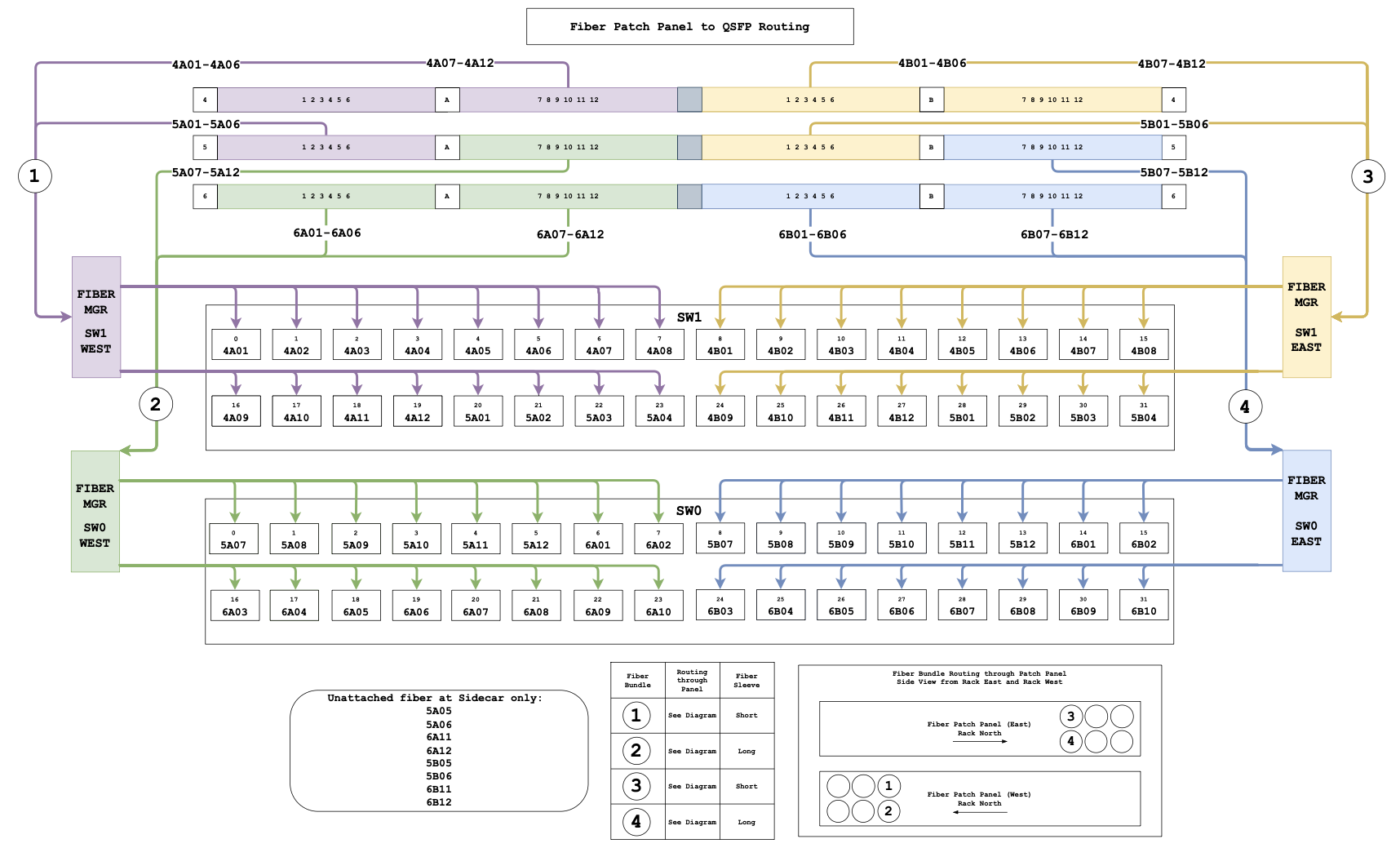
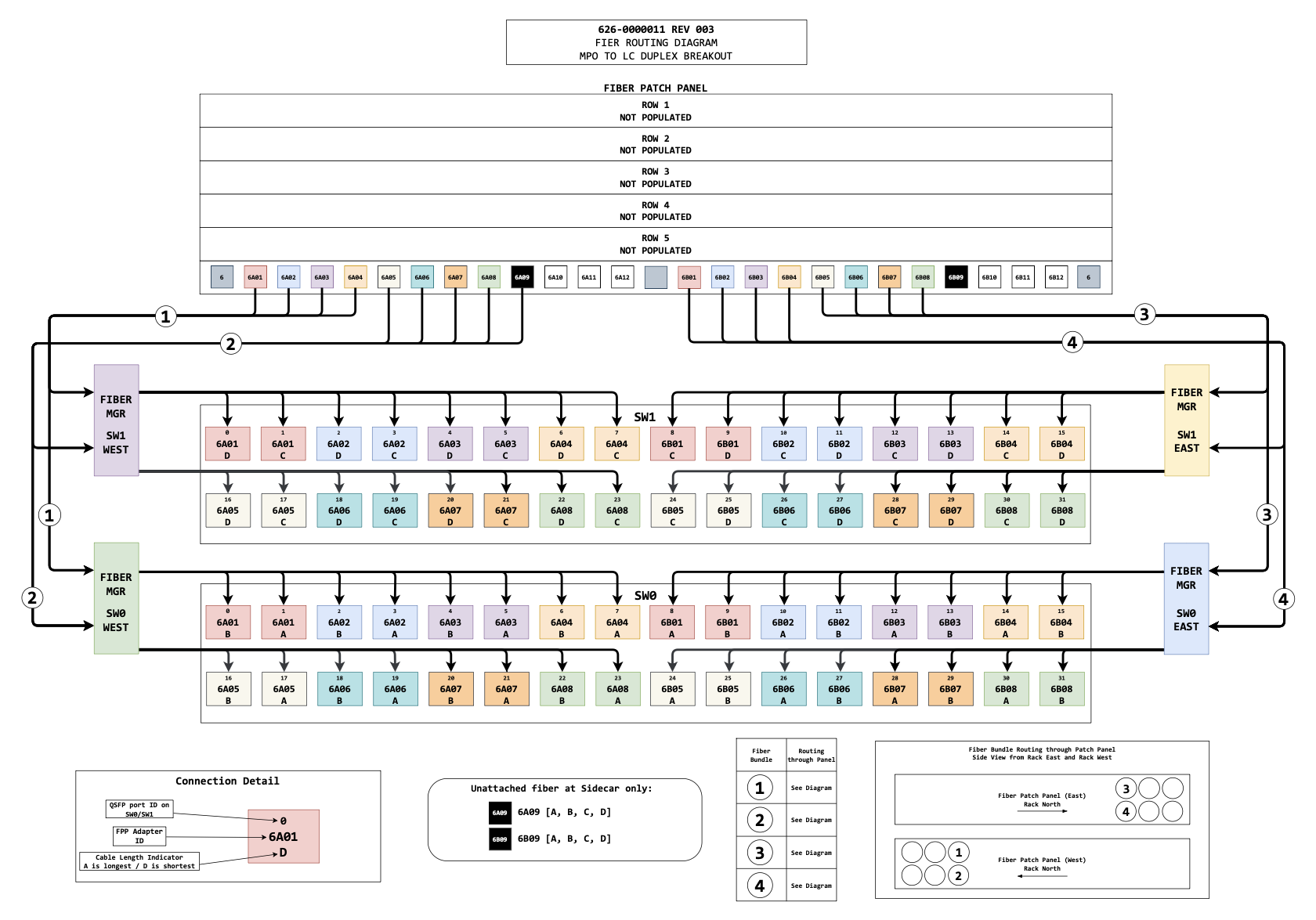
Verify the following:
The switch and QSFP port numbers you are using match what you will configure in the
rack.toml(e.g., if you plug into port 0 on switch 0, you configureqsfp0for switch 0).The fiber connectors are clean — use a fiber cleaning tool if available.
Check transceiver LEDs
Once the uplink connections have been established, verify that the LEDs are lit for the plugged-in transceivers.
An off or blinking LED indicates a physical connectivity issue. Use the following to diagnose:
| Symptom | Cause | Solution |
|---|---|---|
LED completely off. | Unsupported transceiver, not fully seated, or faulty. | Verify transceiver is on the supported list, reseat the transceiver, try a known-good replacement. |
LED blinking. | Intermittent physical connection. | Clean and reseat the fiber, check for bent pins or damaged ferrules. |
LED solid but no link on upstream. | Speed/FEC mismatch with upstream port. | Verify that the upstream port speed and FEC settings match what you will configure (e.g., 100G with RS FEC). |
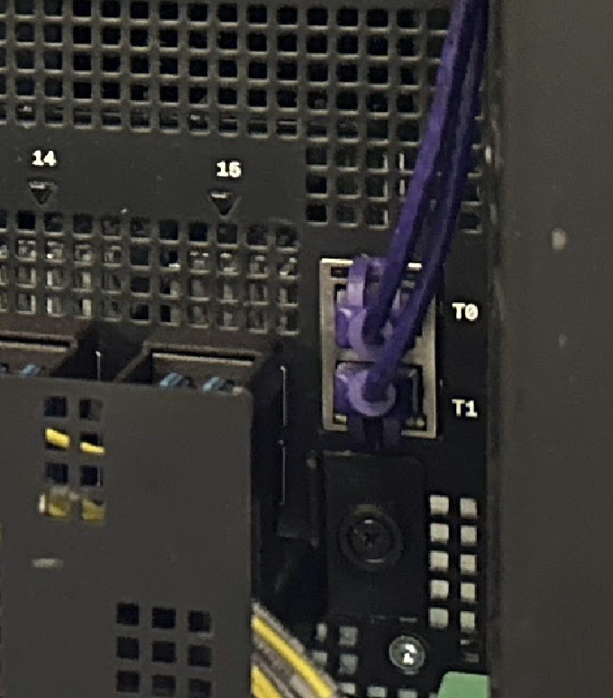
Connect technician ports
Connect RJ45 cables from your jumpbox or technician laptop to the technician ports on the rack switches. Each switch has two technician ports (labeled T0 and T1) on its front panel. They are on the right side of the switch, and are the only RJ45 ports on the front.
Technician port isolation
If both tech port cables are connected to the same physical upstream switch, then that upstream switch must be configured to place them on separate VLANs.
Why isolation matters: If tech ports are not isolated, both switches will advertise IPv6 addresses on the same broadcast domain. This causes:
The Wicket TUI to only discover one switch instead of both.
Race conditions during initialization where the Management Gateway Service cannot reliably determine which switch it’s communicating with.
IPv6 neighbor discovery conflicts that can cause connection timeouts.
Failed rack initialization with errors like "cannot reach scrimlet on switch1" or "MGS connection refused".
When properly isolated, each tech port operates in its own network segment, allowing wicket to discover and communicate with both switches independently.
Verify IPv6 connectivity
The technician ports send out periodic IPv6 SLAAC advertisements. To verify connectivity from the jumpbox or laptop:
Ensure the connected interface is configured for IPv6 autoconfiguration (SLAAC).
Check for received SLAAC advertisements:
ip neighbor show | grep fdb1
You should see output like:
fdb1:a840:2504:195::1 dev eno2 lladdr 02:08:20:36:5c:8d REACHABLE
fdb1:a840:2504:352::1 dev eno1 lladdr 02:08:20:bb:26:4d REACHABLE
Verify SSH connectivity to the wicket shell:
ssh wicket@fdb1:a840:2504:195::1
You should then see an Oxide splash screen. Press
Ctrl-Cto exit for now.
If you do not see any fdb1: addresses:
| Symptom | Cause | Solution |
|---|---|---|
No | IPv6 SLAAC not enabled on the interface. | First verify IPv6 is enabled: |
Addresses appear but SSH times out. | Firewall blocking TCP port 22. | Check firewall rules between jumpbox and tech port network. |
Addresses appear but SSH connection refused. | Switches still booting. | Wait 2–3 minutes and retry. |
Only one address (not two). | One switch cable not connected or tech port isolation misconfigured. | Check the cable to the other switch; verify VLAN isolation is correct. |
- image
macro when ready.
 Figure 3. Troubleshooting: Can’t SSH to Tech Port
Once you have confirmed SSH connectivity to wicket on at least one tech port per switch, the physical installation is complete.
What’s next
Network connectivity is established. Proceed to:
Phase 3: Initial Rack Setup — Component validation, software updates, rack.toml configuration, and rack initialization via wicket (2-4 hours with a network engineer on standby).
Have your Phase 1 Summary Checklist ready — you’ll need the DNS servers, NTP servers, IP ranges, and routing configuration you prepared in Phase 1.